Analog Redial: an ESP32-C6 phone system for old telephones
Scott Dylewski's board turns one or two old rotary or touch-tone phones into a hackable little phone system: dial tone, ringing, dial codes, an answering machine and Home Assistant.
What it is
A board that gives old rotary and touch-tone phones dial tone, ringing, an answering machine and programmable dial codes.
What you need
- ESP32-C6-DevKitC-1
- Analog Redial PCB fab-assembled, from the creator's files
- AG1171 SLIC (one per line)
- 2 A USB-C charger
- 1–2 old analog phones rotary or touch-tone
How hard
Intermediate: order a fab-assembled board, solder the through-hole parts, then flash with ESP-IDF. Setup after that is a web page.
Key Facts
- Controller: ESP32-C6-DevKitC-1 (16 MB or 8 MB; 16 MB leaves more room for recordings) with an ES8388 audio codec and one AG1171 SLIC per phone line
- One or two phone lines; a single-line build can use a microSD card for recordings instead
- Works offline between the two phones; Wi-Fi is for the web interface at phone.local and for VoIP/SIP
- Creator's figures (US, Sept–Oct 2026): about $17 per assembled board from JLCPCB (5-board minimum, $85.53 delivered) plus about $19 of hand-solder parts
- Needs a 2 A USB-C charger or a regulated 5–6 V 2 A DC supply. Never a 9 V or 12 V adapter
- Firmware and docs: MIT licence. KiCad hardware files: no licence grant (personal/hobby use, per the repo's LICENSE)
About This Project
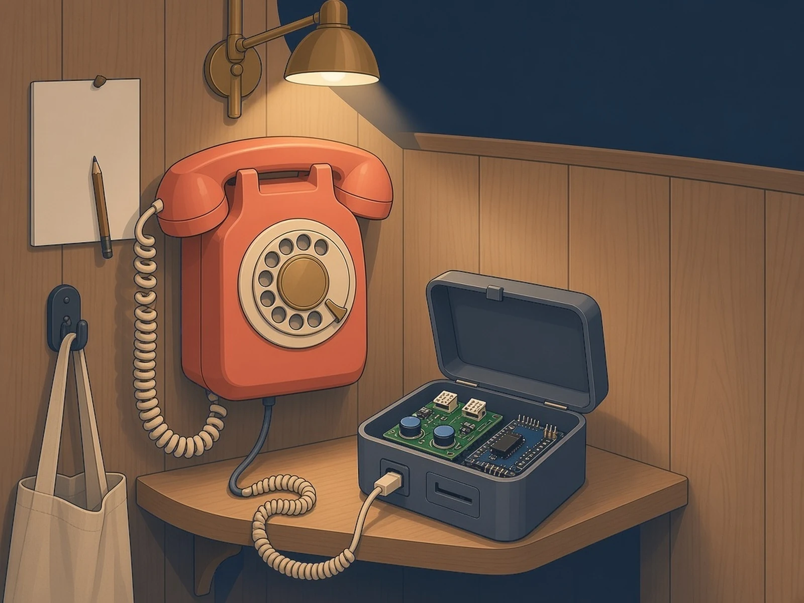
Analog Redial is a small phone exchange for old analog phones by Scott Dylewski (@sdylewski). Plug in one or two rotary or touch-tone phones and they get real dial tone and ringing, can call each other, and gain an answering machine, voice recording and dial codes that do things, all set up from a web page on your network. An ESP32-C6-DevKitC-1 runs the ESP-IDF firmware, an ES8388 codec handles the audio and a Silvertel AG1171 SLIC drives each phone line. It can also make VoIP calls to another board or through a SIP server, report to Home Assistant over MQTT or webhooks, and, with an optional Bluetooth (BM64) board, turn a rotary phone into a handset for your mobile. The board is a 2-layer PCB: a fab assembles the surface-mount parts and you solder the through-hole parts. Hackaday featured it on November 2, 2026.
Source & Attribution
Illustration
Parts Needed
- ESP32-C6-DevKitC-1 (16 MB or 8 MB)
- Analog Redial PCB with SMT parts fitted
- AG1171 SLIC, RJ12 jack and 470 µF capacitor per phone line
- 2 A USB-C charger
- One or two analog phones
- Optional: microSD card (single-line build), Bluetooth BM64 board
Steps
- 1
Get a board
Join the creator's pooled order or upload the KiCad design to JLCPCB with SMT assembly (5-board minimum). The creator's board page says which version to order; v5 is the tested one.
- 2
Choose your build
Decide between two phone lines, or one line plus a microSD card. The J5 jumpers set which one, as the creator's parts page explains.
- 3
Solder the through-hole parts
Fit the DevKit, the SLIC module, RJ12 jack and capacitor for each line, and the headers, following the creator's assembly guide. If you use the cheap 30-pin clone module on a v5 board, take out its bottom-right 5V pin (cut it off or leave it unsoldered): on v5 that pad is ground, so the pin would short 5 V to ground. Check with a meter before power-up. The genuine DevKitC-1 and v5.1 boards are not affected.
- 4
Flash the firmware
Install ESP-IDF, clone the repo and run the creator's flashing script with the USB-C port marked USB. It detects the flash size and builds the right image.
- 5
Join Wi-Fi and set it up
On first boot the board opens its own setup Wi-Fi. Give it your 2.4 GHz network, then open phone.local in a browser to set dial codes, the answering machine, VoIP and Home Assistant.
- 6
Stay safe
The phone ports carry real voltage: about 48 V DC off-hook and about 60 V AC while ringing, with peaks near 90 V. Plug in phones only, never a wall jack or telco line, and power it only from a 2 A USB-C charger or a regulated 5–6 V supply.
Bill of Materials
Parts list
10 parts · 7 linked
Heads up: some Buy links are affiliate links. If you buy through one, MCU Atlas may earn a small commission at no extra cost to you. It never changes which parts we list. How this works
1× ESP32-C6-DevKitC-1 (32-pin)
Third-party listing, not Espressif's store. Its title lists the ESP32-C6-WROOM-1/N8, the 8 MB module: the firmware fits it, with less room for recordings than 16 MB.

1× Analog Redial PCB with SMT parts fitted (includes the ES8388 codec)
1× RJ12 jack, 6p2c (Amphenol 87180-062LF)
1× 470 µF 16 V radial electrolytic capacitor
1× microSD card
1× Bluetooth companion board (BM64 module)
2× Analog rotary or touch-tone phone
Not included: 2×4 pin header (J5), optional DC barrel jack and P6KE82A line TVS diode, optional hacker headers, 3D-printed case (v4 case files in the repo; v5 needs its own), USB-C data cable and a computer with ESP-IDF to flash, Soldering iron (through-hole parts only)
Related Projects